Six Simple Steps for Ordering a Flaming River Steering
System:
1. Choose the type of intermediate shaft you will be
using—Splined or DD. This will determine one side of
the Universal Joint that you will need to order.
2. Determine whether you will need a two or three
U-Joint system. This is dictated by the angle—we
recommend a 15° angle for the optimal setup, however
up to 30° is acceptable. If using a three U-Joint system,
a Support Bearing is necessary. The center U-Joint
should either be 3/4" DD X 3/4" DD or 3/4”-36 X 3/4"-
36 depending on whether you are using splined or DD
shafts.
3. Use the Reference Application Chart to select the
proper Rack and Pinion or Steering Box spline size for
your system. If the chart does not list your application,
just measure the diameter of the shaft and count the
number of individual splines. If there is a flat, count half
of the splines and then double that number.
4. Measure your column’s output shaft. If it is a DD shaft
(two rounds, two flats), then measure the rounds—it
will either be a 1” DD or 3/4" DD. If there are splines,
then measure the diameter and count the individual
splines—it will either be 1”-48 or 3/4”-36.
5. If you are using splined shafts and a two U-Joint
system, then measure the distance between the steering
gear shaft and the column and then subtract 3-1/4”.
Round this number up to the next whole number to
determine the shaft length you require.
6. If you are using a three U-Joint system, we
recommend using dowel rods to mock up the system.
Simply measure the length of the dowel rod and this will
be the length of the shaft you will require. DD shafting
can easily be cut down to size.
Important Notes:
• Phasing – Keep the forks of the yokes closest to each
other in line, and parallel to the center of the shaft to
avoid binding.
• NEVER weld a Universal Joint! Welding reduces the
strength of the metal and can melt the needle bearing
seal.
• Set screws are supplied on all splined and DD
Universal Joints. However, it is necessary to indent,
by drilling, the shaft to properly secure the set screw
mechanism. A red thread locker should also be used.
Periodically inspect the set screws to ensure tightness.
• The shaft should be installed 7/8” into the yoke
(flush). A shaft that does not
engage fully could sacrifice the
strength of the system. However,
if a shaft is too long, it can cause
the shaft to interfere (bind) with
the operation of the system.
Tech Tips
Application Size Spline
Dia.
Spline
Ford Rack
Mustang II & Pinto Manual
Mustang II & Pinto Power
9/16”-26
3/4”-36
.563
.750
26
36
Ford Box
Manual & Power 3/4”-36 .750 36
GM Box Manual
Vega
Corvair
Corvette (63-68)
Corvette (69-82)
Model 122 (65-85)
Model 525 (86 - Present)
5/8”-36
5/8”-36
3/4”-36
3/4”-30
3/4”-30
3/4”-36
3/4”-30
.625
.625
.750
.750
.750
.750
.750
36
36
36
30
30
36
30
GM Power Box
Model 605 (78-84)
Model 800 (77-Prior)
Model 800 (78-Present)
3/4”-30
13/16”-
36
3/4”-30
.750
.813
.750
30
36
30
GM Rack
79-Present
Variations
Corvette (84-Present)
Fiero
5/8”-36
3/4”-30
17MM D
17MM D
.625
.750
.670
.670
36
30
.570
.570
Chrysler Box or Rack
Omni Manual
Omni Power
Power Box
Manual Box
9/16”-26
9/16”-36
5/8”-36C
3/4”-36
.563
.563
.750
26
36
36
36
Misc.
Jaguar & MGB
VW Rabbit - Diesel
BMW
3/4”-48
3/4”-36
17MM-54
.750
.750
.670
48
36
54
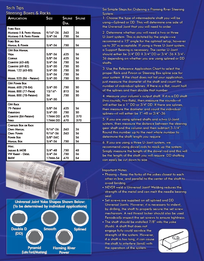
Universal Joint Yoke Shapes Shown Below:
(To be determined by individual applications)
Double D Smooth
Splined
(DD)
Pyramid
(Late Ford/Mustang)
Flaming River
Power
Steering Boxes & Racks